Problem

The summary of the ordering of vertices when using blockMeshDict.

Solution

The ordering of vertices
(This may need correction but works in my case.) The vortices should be arranged in column order, as shown in the following figure.
vertices_order

The ordering of hex
In the OpenFOAM 3_weeks tutorial[1], it clearly says that the vertex order to form a hexahedral should be counter-clockwise. For example,

1
2
3
4
blocks
(
hex (0 3 4 1) ($xcells $ycells $zcells) simpleGrading (1 1 1)
);

This is because the first vertex defines the origin of the block and the first 2 vertices can define the x axis direction. It facilitates the recognition of the block by the code.

The ordering of boundary
When constructing the faces for boundary conditions. Vertices should be arranged in such a way that they need to be neighbors and it does not matter if the ordering is clockwise or counter-clockwise[1].

Summary

The ordering in vertices and hex is important. For boundary conditions, clockwise and counter-clockwise are both acceptable.

Ref

[1] https://wiki.openfoam.com/index.php?title=Day_6

OpenFOAM: inletOutlet boundary and why defining both inletValue and value

The inletOutlet is a generic boundary condition that provides an outflow condition, with specified inflow for the case of return flow[1].

The mode of operation is determined by the sign of the flux across the patch faces[1].

  • Positive flux (out of domain): apply zero-gradient condition.
  • Negative flux (into domain): apply the inletValue fixed-value.

Example:

1
2
3
4
5
6
outlet
{
type inletOutlet;
inletValue uniform (0 0 0);
value uniform (0 0 0);
}

Question:
In the above code block, we have defined the “inletValue” for backflow conditions. Then why do we further define a “value”?

Answer:(from chatGPT, for reference only)
This is a required field in OpenFOAM for any field with a fvPatchField, even if it is not always used directly by the boundary condition logic.

During mesh initialization and when reading field files like U, p, etc., OpenFOAM needs a placeholder value for each boundary. The value field provides this.

In some contexts (like post-processing, writing, or during initial time steps), OpenFOAM may fall back to value if the dynamic logic of the boundary condition is not yet triggered.

Ref:
[1]: https://doc.openfoam.com/2312/tools/processing/boundary-conditions/rtm/derived/inletOutlet/inletOutlet/

I have joined a work far from CFD for now. However, I encountered a task that requires a CFD simulation to reveal the physical process recently. The open-source solution comes to my mind at first priority. I started to install the latest OpenFOAM(12) in my new laptop and then re-learned the key points to implement the simulation. However, the OpenFOAM implementation is far from filling parameters and clicking “Run”. The references are also somewhat scattered on the internet. It takes quite a long time to pick up OpenFOAM again since I did not learn OpenFOAM very deeply, however, it is worth it.

In my task, I want to monitor a variable over the central line at every 10 timesteps. After searching the Internet, I found that this can be realized through the functions utility. However, I didn’t find a direct example. Here I provide my implementation for your reference.(Note: Function objects are OpenFOAM utilities to ease workflow configurations and enhance workflows by producing additional user-requested data both during runtime and postprocessing calculations, typically in the form of additional logging to the screen, or generating text, image and field files.[1])

The functions block can be added in the system/controlDict directory. I was inspired by the discussions on cfd-online[2] and the comments from ufocfd.

Then I searched on Google about the topic “openfoam write variable over a line at every timestep”. The Google AI search gives the following code example:

1
2
3
4
5
6
7
8
9
10
11
12
13
14
15
16
17
18
19
20
21
22
23
24
25
functions
{
mySampler
{
type sample;
libs ("libsampling.so");

outputControl timeStep;
outputInterval 1;

fields (U p T);

sets
(
myLine
{
type line;
start (0 0 0);
end (1 0 0);
nPoints 100;
interpolationScheme cellPoint;
}
);
}
}

It gives me a lot of confidence though the AI generated code does not work generally, especially for OpenFOAM which is not widely used by people worldwide. Whatever, it is a good start. Thank you LLM.

I copied the code into system/controlDict and compile the code. OpenFOAM complains about the code errors, such as the unknown type of sampling. With the “banana” method, I can quickly correct the code block in the following:

1
2
3
4
5
6
7
8
9
10
11
12
13
14
15
16
17
18
19
20
21
22
23
24
25
26
27
28
29
30
functions
{
height_sampler
{
type sets;
libs ("libsampling.so");

executeControl timeStep;
executeInterval 10;
writeControl timeStep;
writeInterval 10;

interpolationScheme cellPoint;
setFormat raw;

fields (alpha.fuel);

sets
(
monitor_line
{
type lineUniform;
start (0.5 -0.2 0);
end (0.5 1.0 0);
nPoints 100;
interpolationScheme cellPoint;
}
);
}
}

Now the monitored data will be stored in the postProcessing/ directory.

In the above code block, sets can define the sampling line I am using. executeControl and writeControl control the implementation of the code block. The interpolationScheme can be referred on the sampling webpage[3]. For example, the “cellPoint” scheme I used applies linear weighted interpolation using cell values.

With the help of LLMs, the development of user modules is greatly accelerated.

Ref:
[1] https://www.openfoam.com/documentation/guides/latest/doc/guide-function-objects.html
[2] https://www.cfd-online.com/Forums/openfoam-post-processing/219747-openfoam-monitor-flow-value-internal-surface.html
[3] https://www.openfoam.com/documentation/user-guide/7-post-processing/7.4-sampling-data

服务器版本docker安装教程

Reference in Chinese:
[1]https://blog.csdn.net/weixin_47425074/article/details/139064776
[2]https://www.cnblogs.com/a120608yby/p/17880004.html

To use docker on Windows Server system, you have to install the “docker-ee” edtion(Docker Enterprise Edition) instead of the desktop client(which is referred to as “docker-ce”) for personal usage.

  • Start and check the “Hyper-V” and “container” services in the server manager of control panel. Restart the server(computer) after this step.
    Container service[1]

  • Download the docker setup package from this link:
    https://download.docker.com/win/static/stable/x86_64/
    An important note: The Windows server system deployed in our group is kind of out of date. Therefore it is important not to download the latest version of docker from the site to avoid Errors in the installation process.

  • Decompress the downloaded file to your desired position and configure the corresponding environment variables:
    Environment variables[2]

  • Register the docker service(Run CMD as administrator)

    1
    dockerd --register-service
  • Start the docker service(Run PowerShell as administrator)

    1
    Start-Service docker

    If no error message appears, the docker is successfully deployed on your system.

  • Configure the daemon.json(For Chinese users only)(创建 C:\ProgramData\Docker\config 目录,在config目录下创建 daemon.json 文件)

    1
    2
    3
    4
    5
    6
    7
    8
    9
    10
        {
    "registry-mirrors": [
    "https://docker.mirrors.ustc.edu.cn",
    "https://registry.docker-cn.com",
    "http://hub-mirror.c.163.com",
    "https://mirror.ccs.tencentyun.com"
    ],
    "insecure-registries": ["127.0.0.1/8", "reg.example.com"],
    "data-root": "d:\\docker"
    }
  • Restart the service (Run PowerShell as administrator):

    1
    Restart-Service docker
  • Set automatic startup:
    Run PowerShell as administrator

    1
    Set-Service docker -StartupType Automatic
  • When docker service fails to start, the “docker engine“ log can be obtained in PowerShell as follows: (For example, incompatibility between docker and my system version is encountered in my case(4 fatal: failed to start daemon: this version of Windows does not support…). The docker log provides clear and helpful information. This tool is really useful.)

    1
    Get-EventLog -LogName Application -Source Docker
  • Reinstall and register the docker service (PowerShell):

    • Stop and remove the current docker service:
      1
      sc.exe delete docker
      This will remove the current docker service, including the accompanying registry entries. To ensure a complete delete, it is then suggested to remove these registry entries manually.
      1
      2
      3
      4
      Press "Win + R" to open the "Run" dialog. Then enter "regedit" to open the Registry Editor.  
      Navigate to the following position:
      HKEY_LOCAL_MACHINE\SYSTEM\CurrentControlSet\Services\EventLog\Application\docker
      Right click the "docker" folder and delete it.
    • Then register the docker service again:
      1
      dockerd --register-service
    • If everything goes well, you can now start the docker service:
      1
      Start-Service docker

Description

In the field of computer hardware, we usually see a word “PCIe” for the motherboard(主板), for example. Here is a note and summary about what is PCIe and how to choose it when we buy computers. The information is collected from the web. Check and support the original posts for full information.

Reference:

About the PCIe hardware

PCI Express (Peripheral Component Interconnect Express,外部设备快速互联), officially abbreviated as PCIe or PCI-e, is a high-speed serial computer expansion bus standard, designed to replace the older PCI, PCI-X and AGP bus standards. It is the common motherboard interface for personal computers’ graphics cards, sound cards, hard disk drive host adapters, SSDs, Wi-Fi and Ethernet hardware connections. PCIe has numerous improvements over the older standards, including higher maximum system bus throughput, lower I/O pin count and smaller physical footprint, better performance scaling for bus devices, a more detailed error detection and reporting mechanism (Advanced Error Reporting, AER), and native hot-swap functionality. More recent revisions of the PCIe standard provide hardware support for I/O virtualization.[1]

In its simplest form, PCIe is a point-to-point connection between two PCIe compatible devices, typically a motherboard and an expansion card or storage device such as an SSD or hard drive. The connection uses differential signaling to transmit data over separate pairs of copper wires.[2]

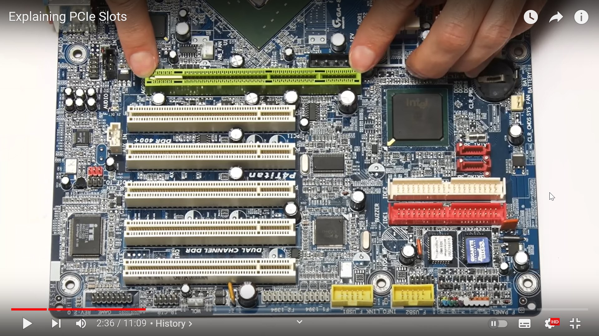
To ensure optimal performance and compatibility across multiple devices, the PCIe standard uses different lane sizes(通道尺寸) which can link together two or more components at once depending on their speed requirements. For instance, larger lanes such as x16 are typically used for graphics cards that require lots of bandwidth for high resolution content; while smaller lanes like x1 are reserved for lower speed peripherals like USB ports or SATA ports.[2] Here is a typical PCIe slot from reference [3].
a typical PCIe slot

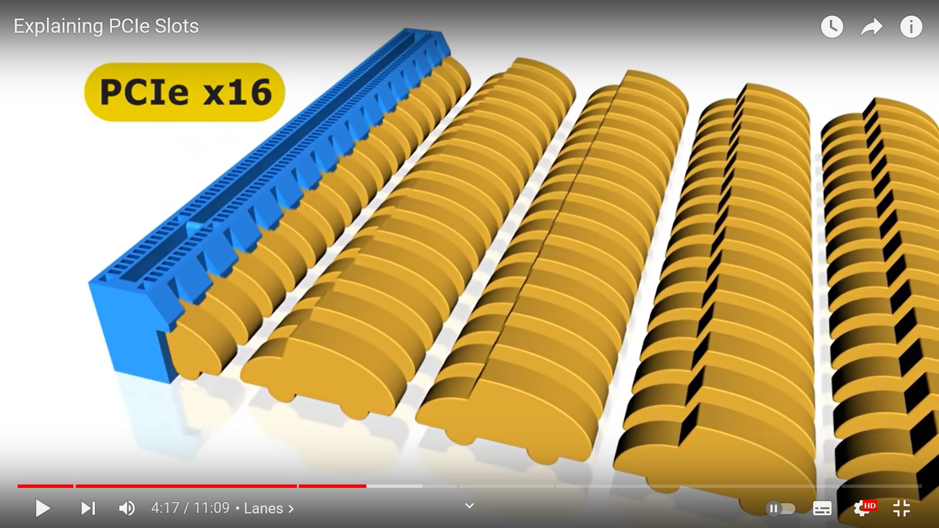
We usually see the name of a PCIe slot as “PCIe 5.0 x16” for example. It means the slot is in PCIe 5.0 standard and the lane size is 16 times the PCIe x1 (usually the larger the slot will be). The higher the standard, the faster the transmission is. Also, the larger the lane size, the more data can be transferred at the same time. Here is a figure showing the concept from ref[3].
PCIex16
Here is the PCIe standard table and the corresponding speeds[3].
PCIe_standard

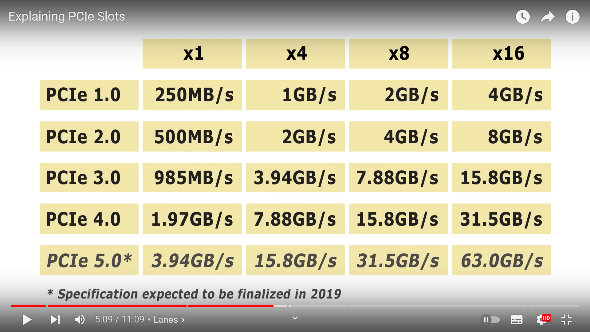
Usually, different PCIe standards are compatible with each other. The data transfer speed is limitted by the lower speed hardware. Note that PCI and PCIe are not compatible with each other. This is because the two protocols(协议) use completely different interfaces that feature different pin configurations as well as varying bus speeds and features – as a result, hardware developed for one protocol will not work properly on the other.

How to choose a PCIe hardware?

As shown above, the higher the standard, the faster the transmission is. Also, the larger the lane size, the more data can be transferred at the same time. Also, different PCIe standards are compatible with each other if needed.

路由器简单结构及购买注意事项,本文摘录自电脑吧测评室公众号,仅对个人认为重要的部分总结,全文请移步和支持: 路由器如何选择、什么是好的路由器 8.0 (https://mp.weixin.qq.com/s/fQw5gkHOmoLjT8wxS0e62g)

路由器的基本组成(图自电脑吧测评室):
路由器基本构造
这个思维导图基本上就包括了一个路由器的硬件结构,从WAN口进入到LAN口或者无线网出所需要的硬件,其中红色字体为必须「可以理解为最低配置」,其余为可选配置

  • 5G热点,很多主控都集成了5G的控制器,但是主控自身集成的信号源会比5GWIFI芯片+FEM 处理过的信号差很多,因此一般有独立5G WIFI芯片+放大电路的路由器在信号强度上就强于SOC直出
  • 同理,SOC内部一般也可以集成一定大小的内存「32M、64M这种」,对比独立的RAM来说,虽然物理空间离SOC更近,但是实际上速率和容量都偏小,路由器的RAM目前正常都在1G或者512M,大一些的也有2G
  • ROM同样也有大小区别,从8M到512M都有,对应就是支持的固件大小和功能丰富性,对于一些路由器来说256M以上的大小可以刷一些第三方的系统或者安装更多的插件实现更丰富的功能。
  • 另外,一些低端路由器SOC集成功能较多,所以相对发热量也会集中,但是又因为是低端路由器,所以一般而言散热也会有一定程度的缩水,对于硬件来说就是火上浇油了,很容易过热。有很多路由器其实硬件本身是属于‘能用’的,但是因为散热缩水,所以SOC或者其他芯片长期运行在高温环境下,因此触发降频,导致出现无线网卡顿、丢包、断流等情况,因此判断一个路由器好坏,散热也是不可缺少的
  • 品牌 TP-Link: TP没别的特色,始终钟爱这种指甲盖大小的陶瓷散热片,实际散热能力接近裸奔「目前为止,TP还有路由器用这种陶瓷块」。另外这个路由器,虽然有2.4G和5G的WIFI芯片,但是芯片直接裸奔的,并且没有FEM或者屏蔽罩等措施,8根天线均为焊接连接,基本上就是缩水的典型~~~你说硬件很差吧,其实也没有很差,但是表现就很狗屎,因为一直过热降频,不改散热没法用。介于TP的优良传统,所以在买了一堆TP路由器之后,这个牌子我彻底拉黑了

总结:应该购买部件分离设计、考虑电路屏蔽、考虑散热的路由器,如中兴路由器

Description

We usually use the “Tab” key for quick indention in code writing. However, the Tab key(tabulator key) is not equal to indention. Particularly in Python, using Tab for indention may cause complication error. Here is how to make the Tab key be equivalent to 4 spaces for indention in Python.

Solution

I use the vim editor to write code. Therefore, go to the ~/.vimrc configure file and add the following code:

set shiftwidth=4 smarttab
set expandtab

Then source ~/.vimrc to make it happen.
set shiftwidth=4 This sets the number of spaces for each level of indentation to 4. When you press the Tab key or use automatic indentation, Vim will insert or remove spaces in multiples of 4.
set smarttab When this option is set, Vim will use the shiftwidth value (in this case, 4) for shifting, but it will use the tabstop value for inserting actual tab characters. If smarttab is not set, the Tab key inserts spaces based on the shiftwidth value.
set expandtab This option is used to make Vim insert spaces instead of actual tab characters when you press the Tab key for indentation. When expandtab is set, Vim replaces tabs with spaces according to the shiftwidth value.
(From ChatGPT-3.5)

Expansion

The tab key Tab (abbreviation of tabulator key or tabular key) on a keyboard is used to advance the cursor to the next tab stop.
The word tab derives from the word tabulate, which means “to arrange data in a tabular, or table, form.” When a person wanted to type a table (of numbers or text) on a typewriter, there was a lot of time-consuming and repetitive use of the space bar and backspace key. To simplify this, a horizontal bar was placed in the mechanism called the tabulator rack(制表机架). Pressing the tab key would advance the carriage to the next tabulator stop. The original tabulator stops were adjustable clips(夹子) that could be arranged by the user on the tabulator rack. Fredric Hillard filed a patent application for such a mechanism in 1900.
(From Wikipedia: Tab key)

Description:

I use a supercomputer to generate PPM(Portable Pixmap Format) high resolution image flows for simulation results. Convert it to a mp4 movie is desirable because the mp4 file is small and plays automatically when opened. ffmpeg is a very powerful tool to convert image/video format, but its commad parameters are very cumbersome. Here is the ffmpeg command to generate the mp4 file.

Command

1
ffmpeg -f(convert format) image2pipe(ppm figures to stream pipe) -vcodec(the decoder) ppm -i(input file) movie.mp4.ppm -vf(the video format) "scale=1024(don't be too large):-1(keep the aspect ratio), format=yuv420p(a color scheme different from RGB)" movie.mp4(the destination file)  

Description:

Since the opensource CFD software Basilisk has been updated to a stage that possesses so many new features, a new learner should follow the offical website and use the new version. However, if you have used Basilisk for a while and want to keep consistency of the software version, like me, this post may help because the installation guide may change with the software updates. This post shows how to install an older version of the software and relating packages such as the gl libary. This is a short summary of the old offical installation guide.

Installation and compilation of Basilisk

  • Firstly, we download the source code and extract the files.
    1
    2
    wget http://basilisk.fr/basilisk/basilisk.tar.gz
    tar xzf basilisk.tar.gz
  • Next, we compile the source code with gcc(a C99-compliant compiler) and make utility.
    1
    2
    3
    4
    5
    6
    cd basilisk/src
    export BASILISK=$PWD
    export PATH=$PATH:$PWD
    ln -s config.gcc config #create a link config to the file config.gcc in the current directory.
    make -k #(--keep-going) Continue as much as possible after an error.
    make
  • Next, we add the installation directory to the environment variables in $HOME/.bashrc
    1
    2
    3
    cd basilisk/src
    echo "export BASILISK=$PWD" >> ~/.bashrc
    echo "export PATH=\$PATH:$BASILISK" >> ~/.bashrc
    Don’t forget to source ~/.bashrc to make the variables work.
  • If we see the complier information after typing qcc --version, the Basilisk software is installed and compiled correctly. For example,
    success

Installation and compilation of bview

The latest Basilisk uses jview and the default web browser to post-process results, however, it is not very convinent to connect to the Basilisk server all the time for many users like me. I would like to use the old bview instead. Here is how to install the libraries related to bview.

  • Firstly, we install the gl related libraries
    1
    sudo apt-get install libglu1-mesa-dev libosmesa6-dev
  • Next, go to the gl directory and compile the files
    1
    2
    cd $BASILISK/gl
    make libglutils.a libfb_osmesa.a #The .a files are the target files by make according to the Makefile.
  • If a graphics card is available on the computer, we can install the related libraries
    1
    2
    3
    sudo apt-get install libglu1-mesa-dev libglew-dev libgl1-mesa-dev
    cd $BASILISK/gl
    make libglutils.a libfb_glx.a

Some additional information

Standalone installation

The libraries are independent from Basilisk and can be installed separately. This is useful for example when running on supercomputers which do not have Basilisk installed.

  • On the local system(eg: personal computer)
    1
    2
    3
    cd $BASILISK
    tar czvf gl.tgz gl
    scp gl.tgz login@supercomputer.org:
  • On the remote machine
    1
    2
    3
    tar xzvf gl.tgz
    cd gl
    make clean
    and then follow the installation instructions above.

Installing OSMesa/GLU from source

1
2
3
4
5
6
7
8
9
10
11
12
13
wget http://basilisk.fr/src/gl/mesa-17.2.4.tar.gz
tar xzvf mesa-17.2.4.tar.gz
cd mesa-17.2.4
./configure --prefix=/home/popinet/local --enable-osmesa \
--with-gallium-drivers=swrast \
--disable-driglx-direct --disable-dri --disable-gbm --disable-egl
make
make install
wget http://basilisk.fr/src/gl/glu-9.0.0.tar.gz
tar xzvf glu-9.0.0.tar.gz
cd glu-9.0.0
make
make install

Welcome to Hexo! This is your very first post. Check documentation for more info. If you get any problems when using Hexo, you can find the answer in troubleshooting or you can ask me on GitHub.

Quick Start

Create a new post

1
$ hexo new "My New Post"

More info: Writing

Run server

1
$ hexo server

More info: Server

Generate static files

1
$ hexo generate

More info: Generating

Deploy to remote sites

1
$ hexo deploy

More info: Deployment

0%